- The 04KN009 -
("04КН009" in Cyrillic letters)
A replacement project
by Erik Baigar, erik@baigar.de, 2010
...modified, 2/8/2012 & 6/12/2017.
The Story
The Replacement V3
The way and lessons learned
Related information
Source for original parts
Future
Datenschutz
Impressum
The 04KN009 is a hybrid micro circuit used on various different instruments
manufactured
in the former USSR. It used there and exported to many related countries
(e.g. the GDR):
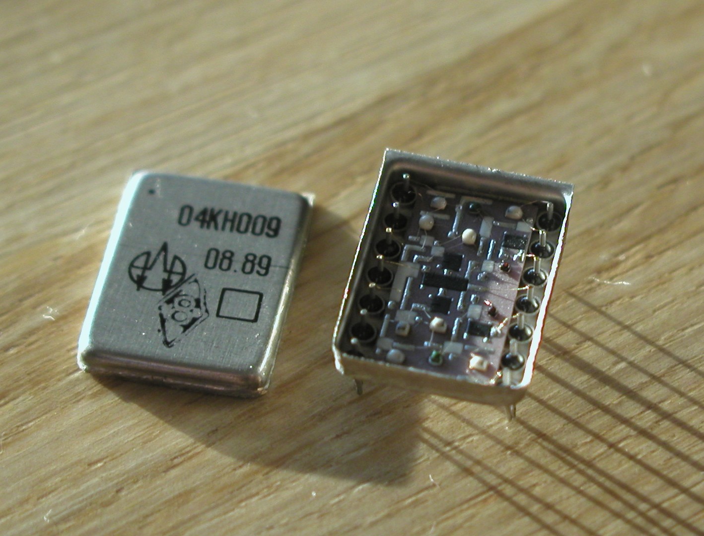
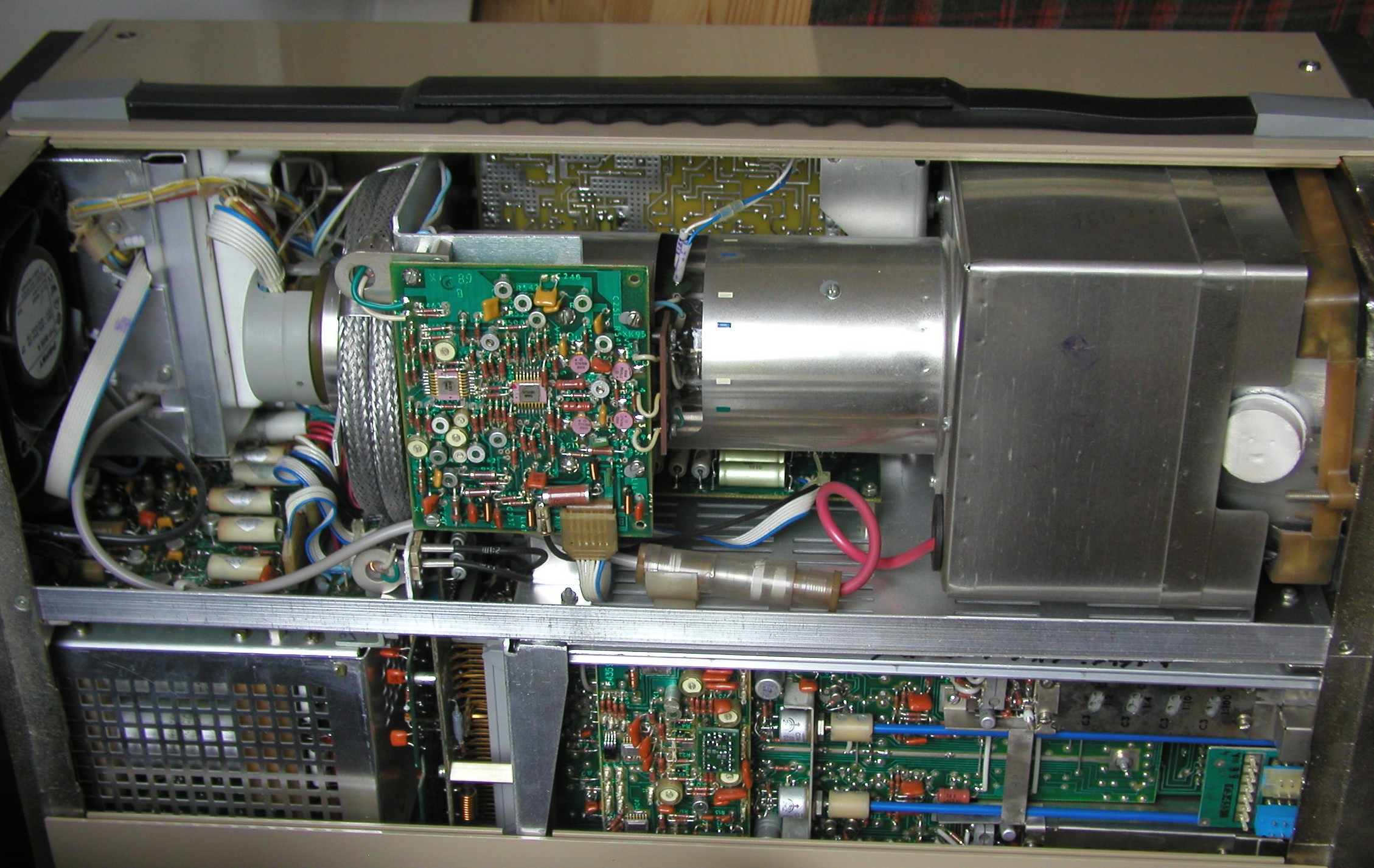
I encountered this small little beast in a C1-122 oscilloscope which I
used for many
years without problems. This oscilloscope is a four trace, 100MHz, strictly
analog
oscilloscope which is similar to some Tektronix equipment from that
era:
To aid other people to keep their oscilloscopes up and running I scanned
the manuals
including schematics and part lists. Here are the links to the pdf
files (German language):
C1-122 Base Frame (8MB0)
Я4C-90 Amplifier
(3M7)
Я4C-91 Time-base
(5M7)
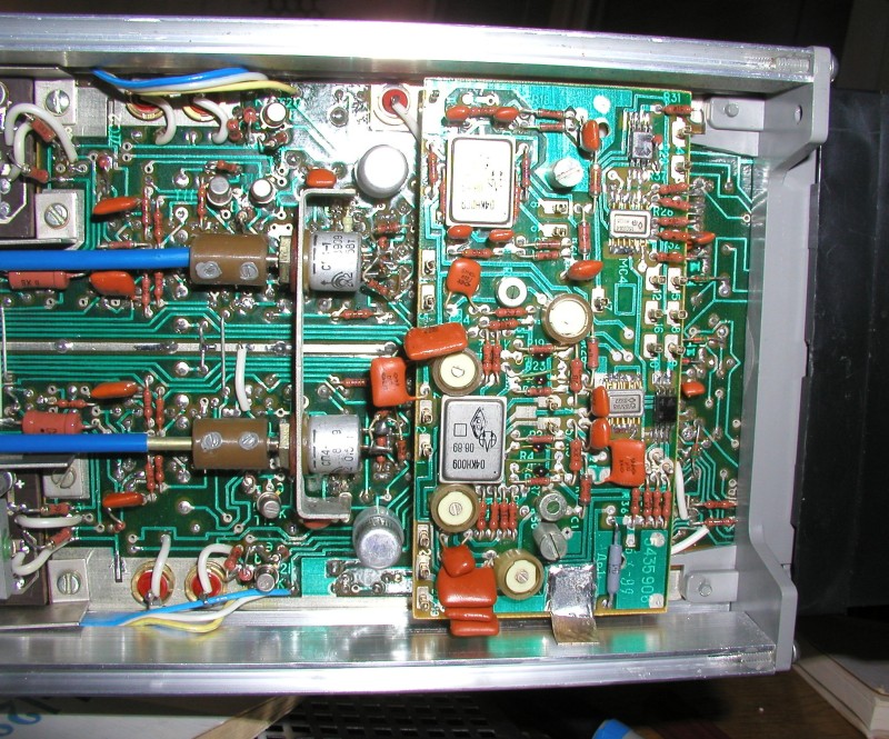
The C1-122 makes use of the 04KN009 as a "commutator circuit". Essentially
they are
acting in the differential signal path as analog switches to route
e.g. one of the two channels
to the output of the amplifier module and to select which channel of
the amplifier module the
trigger "listens" to. So there are two 04KN009s in each Y amplifier:
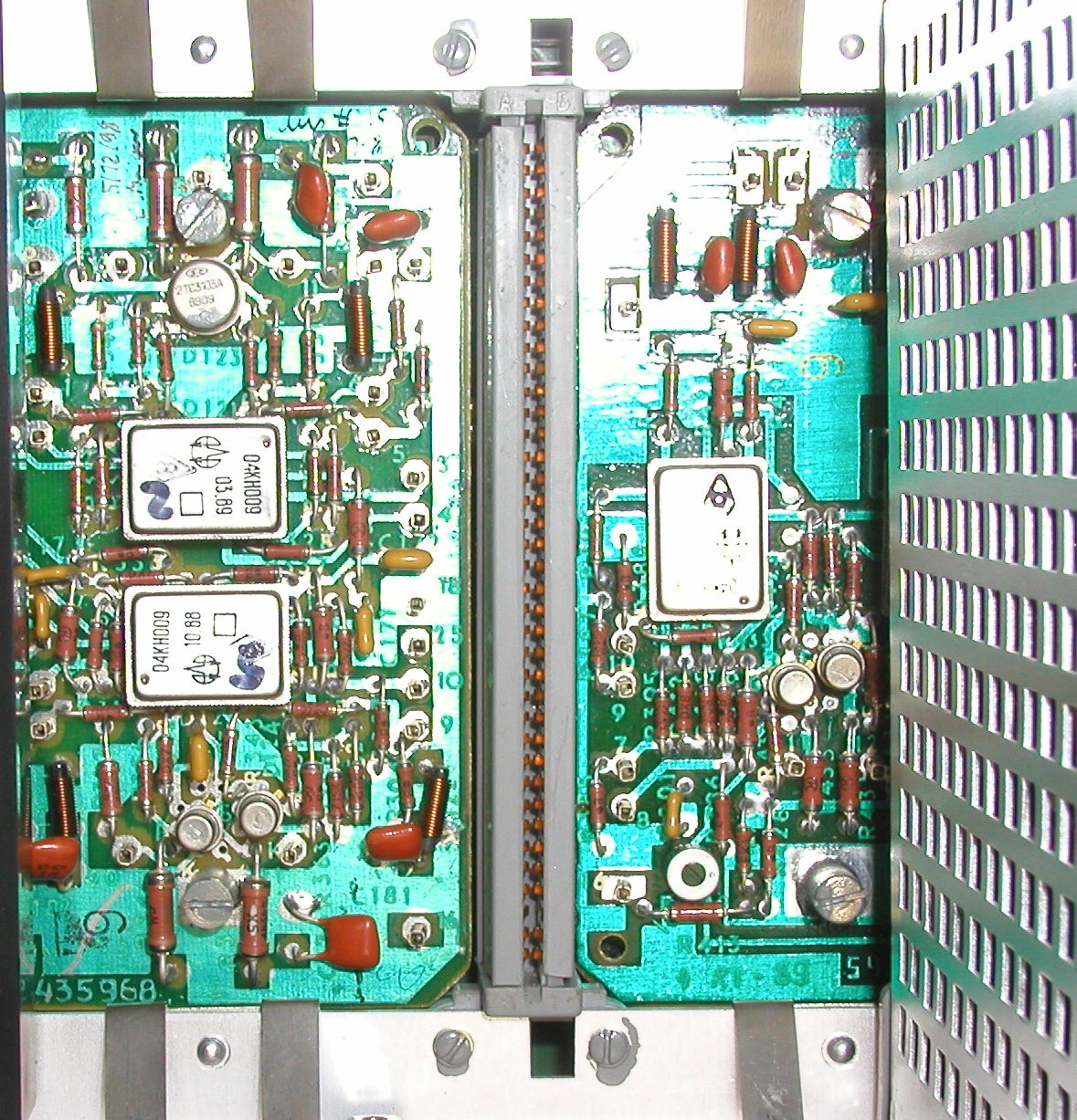
The same circuit is used within the base frame to select which module's
output is routed
to the display or which module's trigger signal is used by the deflection
plug in. So there
are another two of the 04KN009 on a small "piggy back" PCB within the
base frame:
Of course in the alternating mode, the 04KN009s switch continuously
between the two
channels or modules to allow simultaneous display of up to four traces
on the display of
the C1-122. So far everything was fine...
In about 1996 suddenly the 04KN009 micro circuits started to die. But
as I had a second
oscilloscope I was able to keep one running until the 04KN009s got
used up. Interestingly in
my case the hybrid circuits dating from 1989 and 1990 died first.
In a research phase I investigated the internals of the 04KN009 which
are printed within
the manual of the amplifier module Я4C-90:
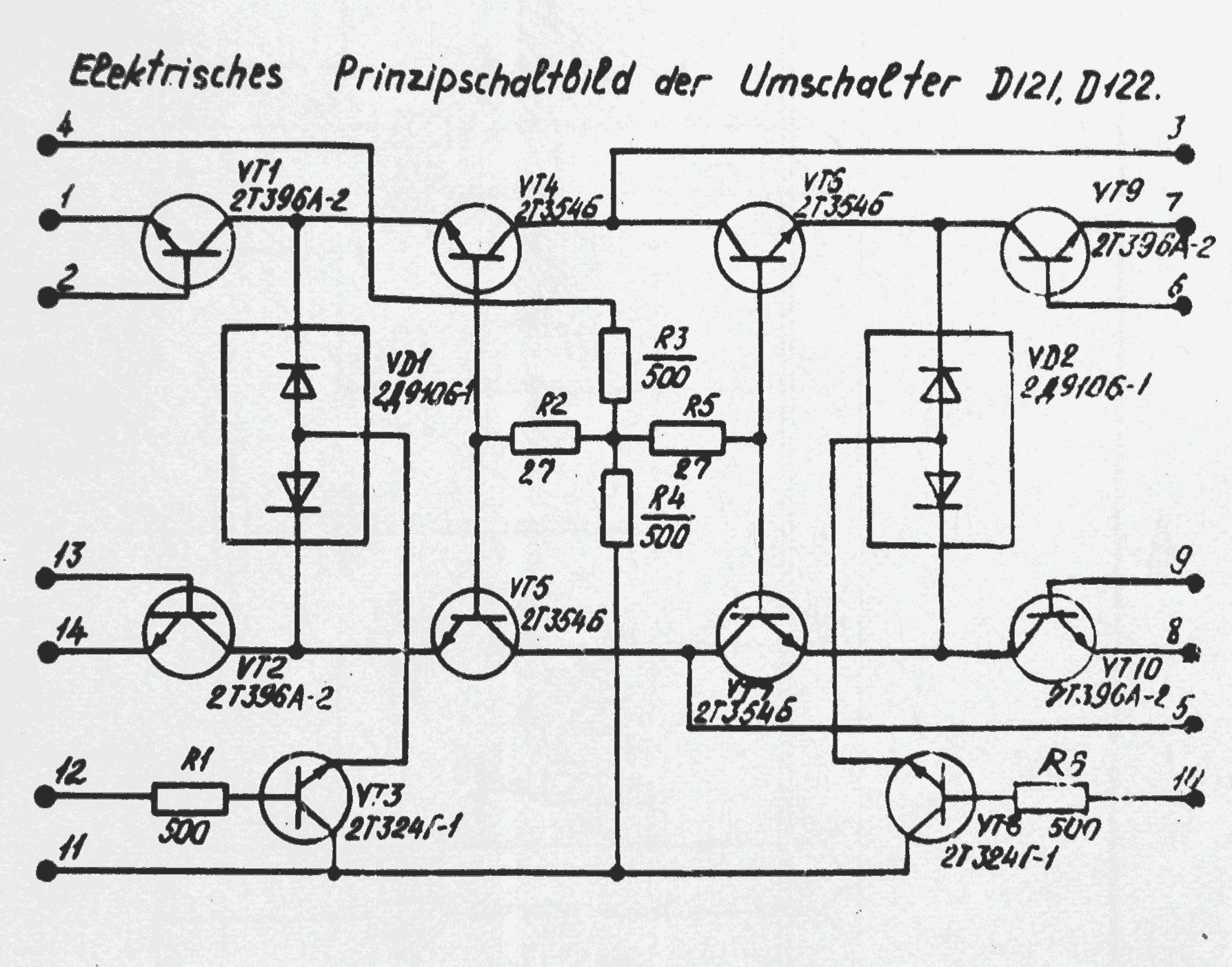
Datasheets
of transistors used where kindly supplied by Gerald Staats, who also en-
countered the same problems with
his scope as I did. He also found a different version of the
schematic of the 04KN009's internals
in Cyrillic letters:
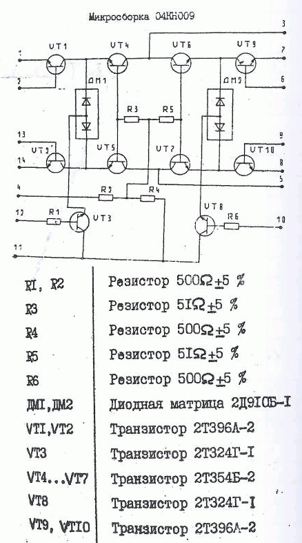
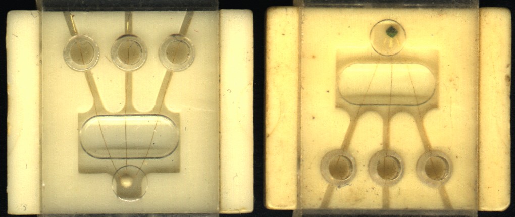
There are two different types of transistor inside which can be distinguished
by the white or green color
of the silicone droplet protecting the wires bonded to the chip. I
got some spares of these transistors from
Holm Tiffe (thanks a lot!). But I was not able to replace the failed
transistors in one of these circuits because
everything is very fragile and special equipment would be helpful.
Here you can see the transistors in their
tiny protective packing:
Taking into account the number of 04KN009s needed (6 for one C1-122), my decision was that
the best
way to solve the problem is a replacement PCB holding the same circuit
as the 04KN009
but utilizing bigger and readily available SMD parts...
After some unsuccessful attempts and many lessons learned (see below),
the version 3
of the a replacement circuit is working in my C1-122 in 6 instances
(two in each vertical
amplifier and two in the base frame). Here you can see what the installed
replacements
look like:
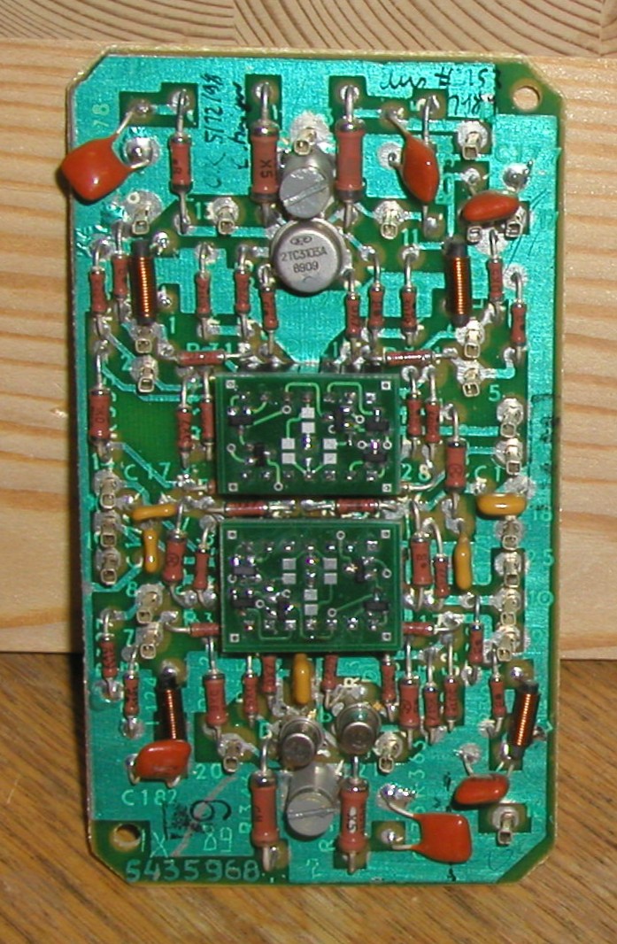
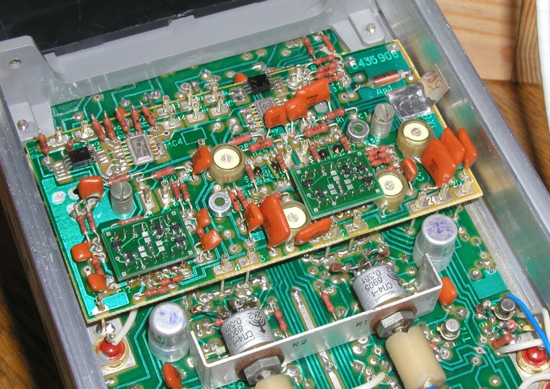
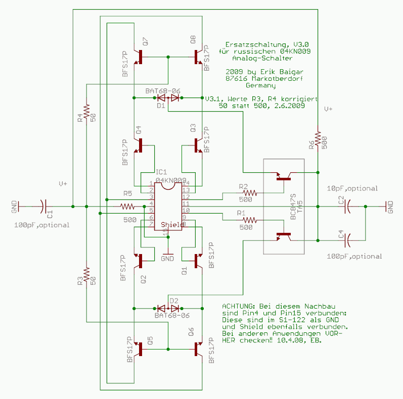
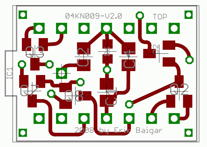
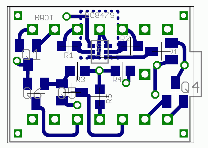
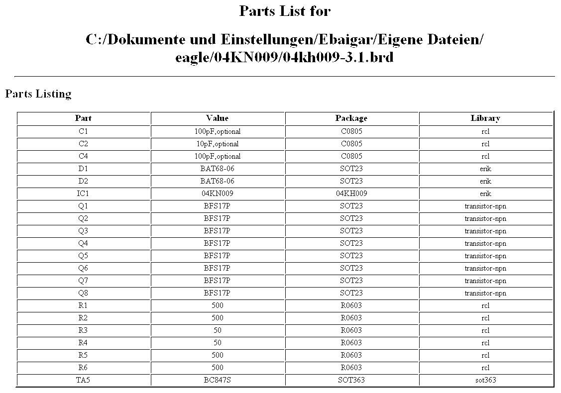
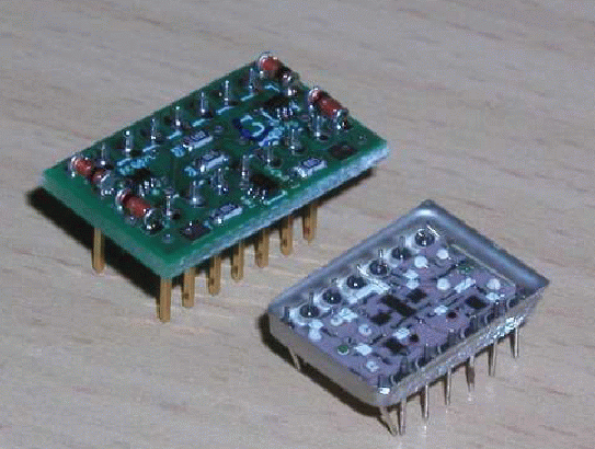
The replacement consists of a small 4-layer PCB with some SMD components
and from
the following pictures you can see the layout, the schematic, the part
list and how the small
PCB is to be installed e.g. on the commutator PCBs
(EAGLE data for V3.1):
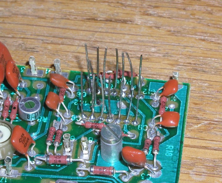
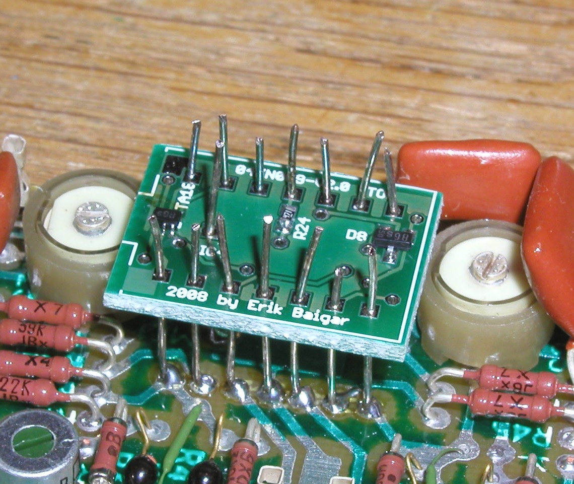
The installation is done by removing the old 04KN009 and soldering wires
into the PCB.
Afterwards the replacement is soldered onto the wires. Take care to
connect the shielding
pin in the middle as well and keep the wires as short as possible since
we are dealing with
RF well above 100MHz. In some early experiments I used sockets, but
this had a negative effect
on signal quality:
To look at the performance of the replacement one can connect a RF sweeper
to the input
and apply a RF ranging e.g. from a few MHz up to 250MHz and sync the
oscilloscope to the
sweeper. You will get pictures like this:
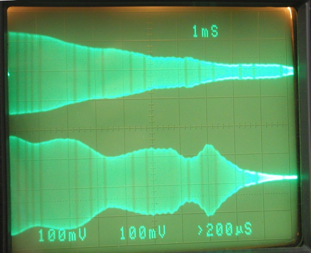
The upper trace shows the signal of the left vertical amplifier (in
this case still
using an original 04KN009) whereas the lower trace originates from
the left amplifier
with the V3 replacement. Both modules get the same RF input and the
horizontal scale
is 25MHz per division. You will notice, that the frequency response
of the original
04KN009 is much smoother than what the replacement does. This is due
to the fact,
that there is a fancy compensation network around the 04KN009 which
is not suitable
for the replacement. But by using the available adjustments, the picture
can be improved
to the following:
Further improvements would require severe changes in the surrounding
tank
and compensation networks which I simply had not time for until now.
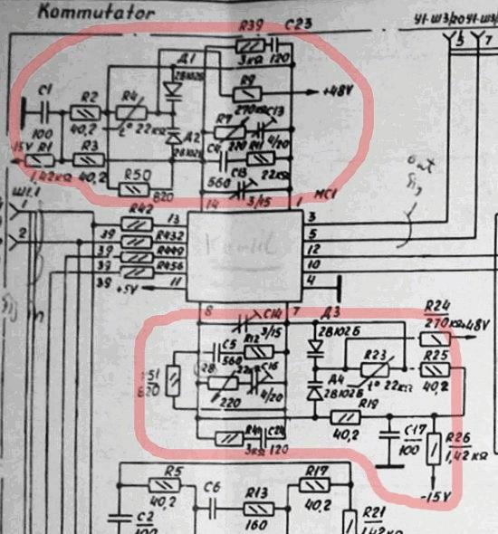
There is a substantial
amount of circuit dedicated to this issue in the vertical amplifier
module (marked in red here):
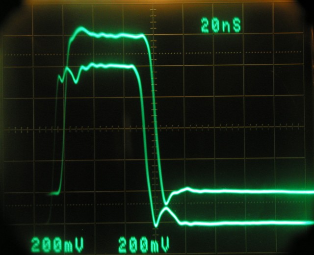
The frequency response of the replacement is always better than of the
original, but it is not as
smooth. This leads to somewhat faster slopes but little more ringing
if a square signal is applied.
The following photograph illustrates this where the upper trace again
is from the amplifier
with the original 04KN009 and the lower trace is the replacement's trace:
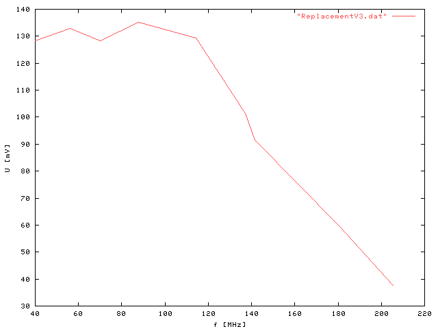
The -3dB point of the replacement is around 160MHz which is sufficient for my application
of
this oscilloscope (for faster measurements I use a HP54542A and the 04KN009
has -3dB @ 150MHz):
3. The way and lessons learned...
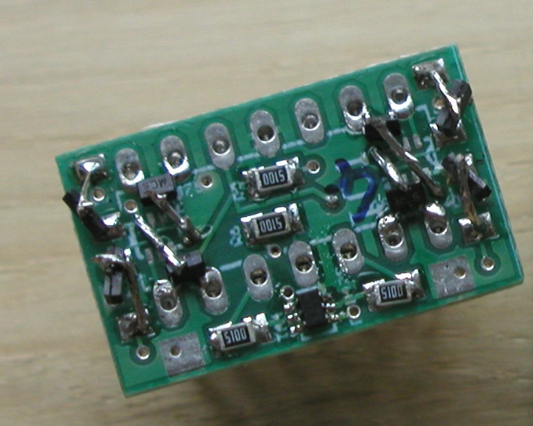
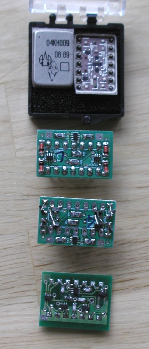
The first version of the replacement used dual transistors (BC874S) to achieve good thermal
coupling (low drift) and 1N4148 diodes as switches. A layout was compiled onto a small
dual layer PCB:
Technical details and assembly instructions can be found in the V1.0-File for reference. It soon
became apparent, that the BC847S are way to slow and although the frequency
response was
very nice, the oscilloscope only had 50 MHz bandwidth (-3dB) with the
V1.0 replacement
installed in the Y amplifier. As a consequence I built a
small test PCB, duplicating the setup within
the oscilloscope's commutator
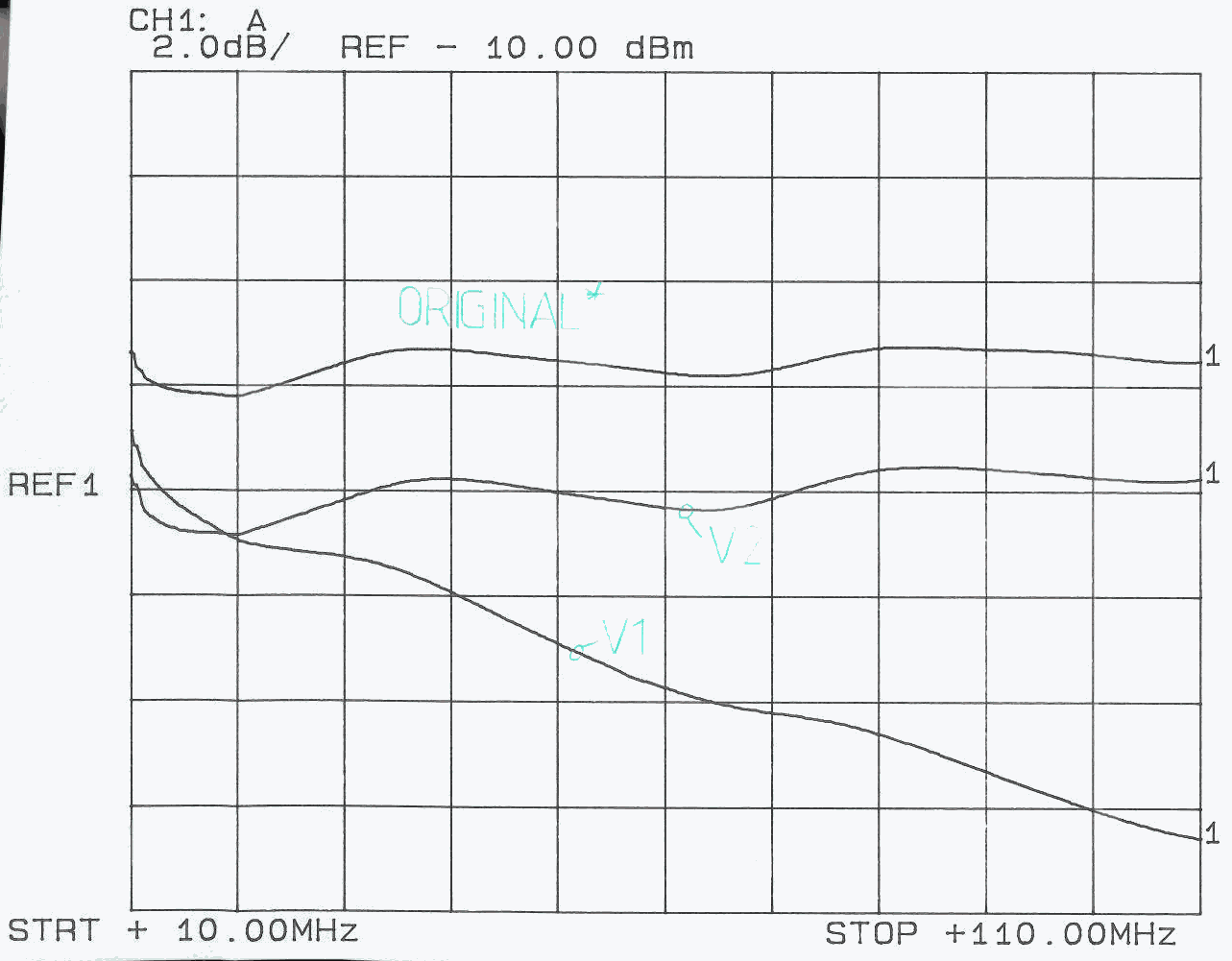
circuit and using baluns for in- and output. This allowed me to "sweep"
the replacements and to optimize and check the frequency response. The
result was a
patched
V1.0a showing good spectral
characteristics and higher -3dB frequency:
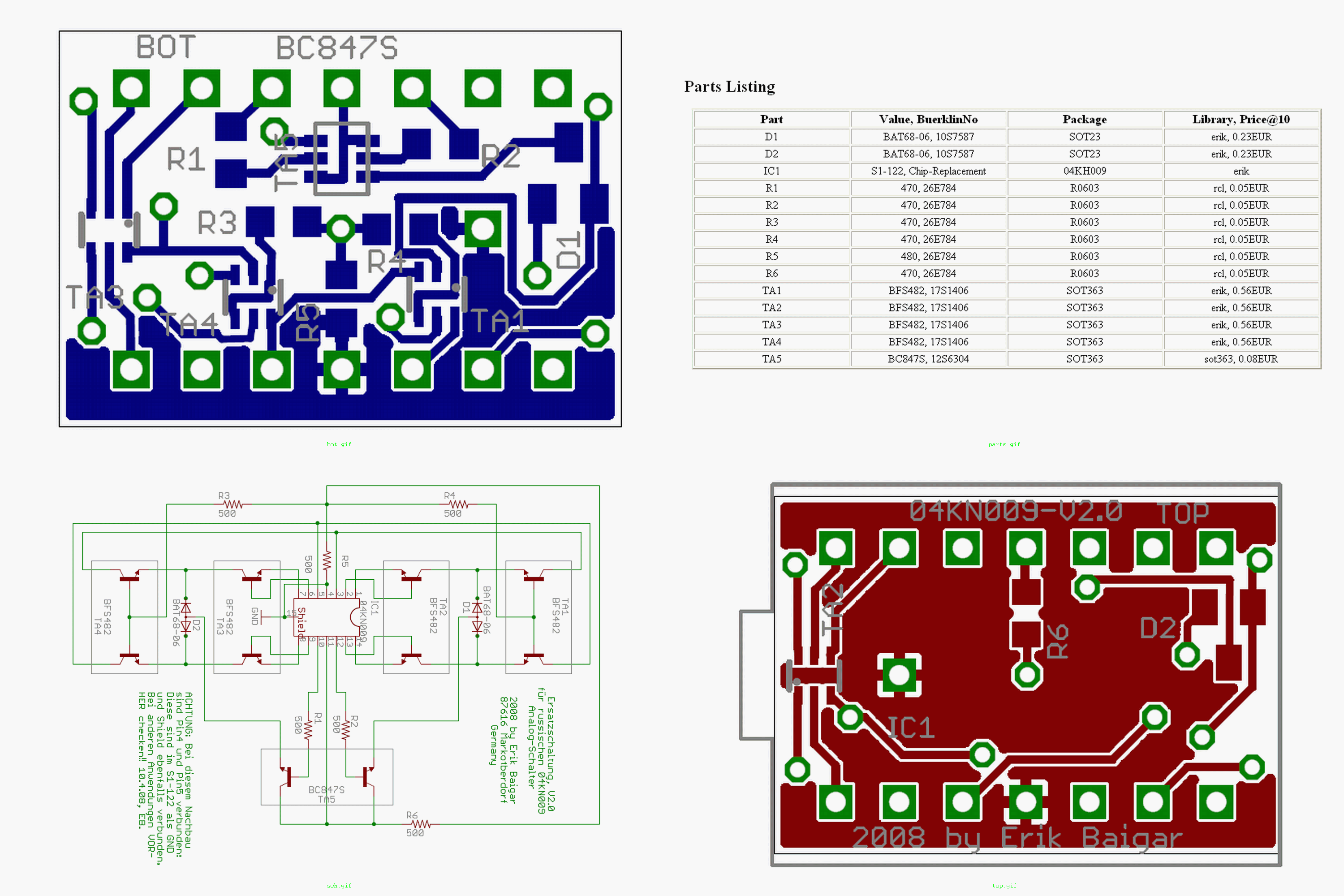
In the next step, the patched V1.0a was converted into a new design: A
4 layer PCB with
continuous ground plane and using the new BFS17 transistors
and fast PIN diodes.
The BC847S dual transistor is still used as a driver transistor
here:
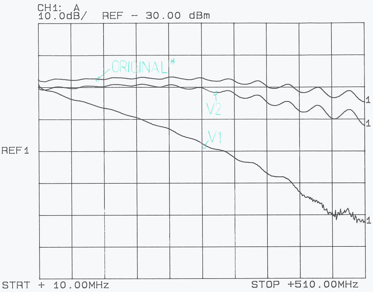
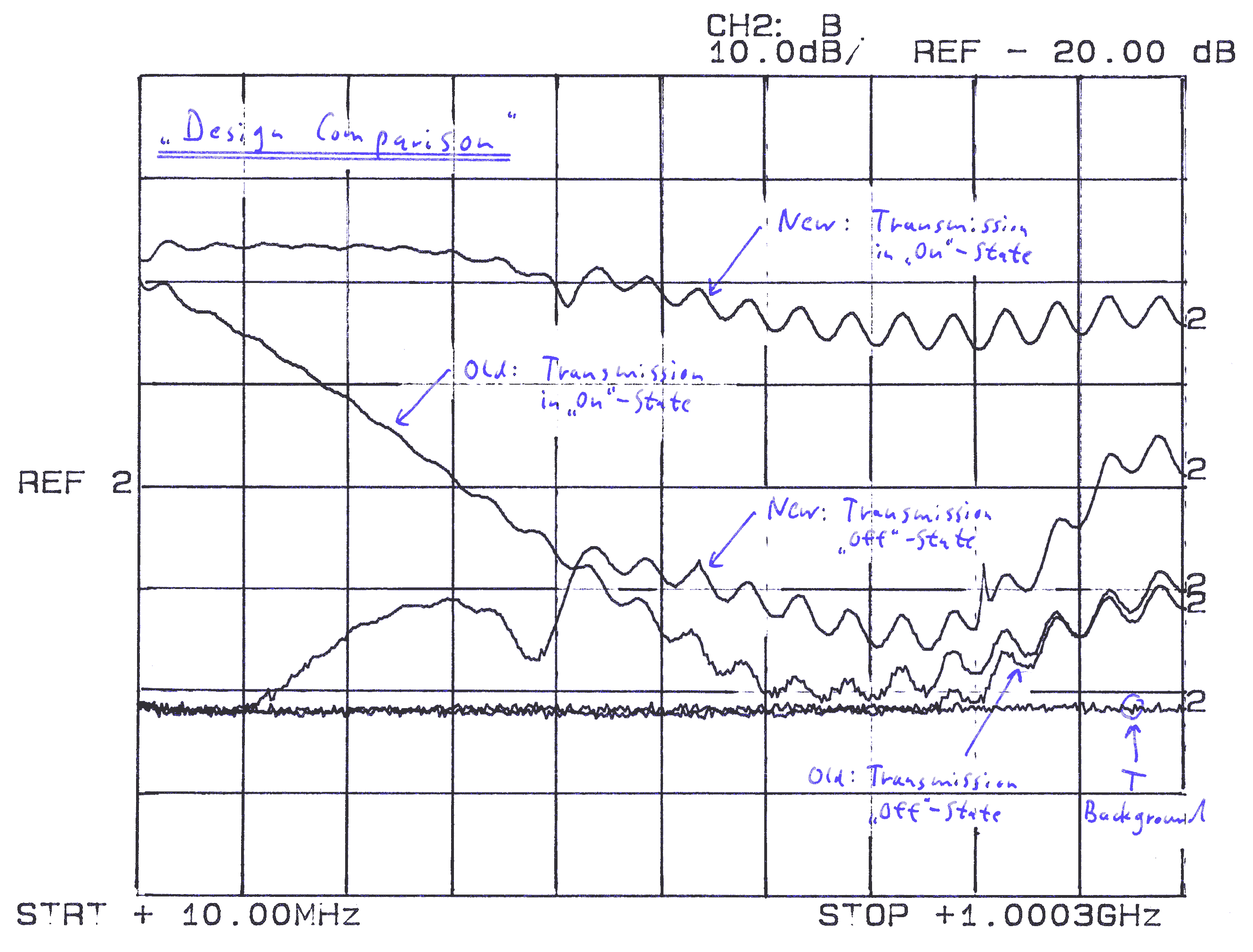
The frequency sweeps show the now much better frequency response (The small
wiggles
are caused by the small test PCB and the baluns which obviously are
not perfectly matched to the
impedance of the 04KN009 or the
replacements):
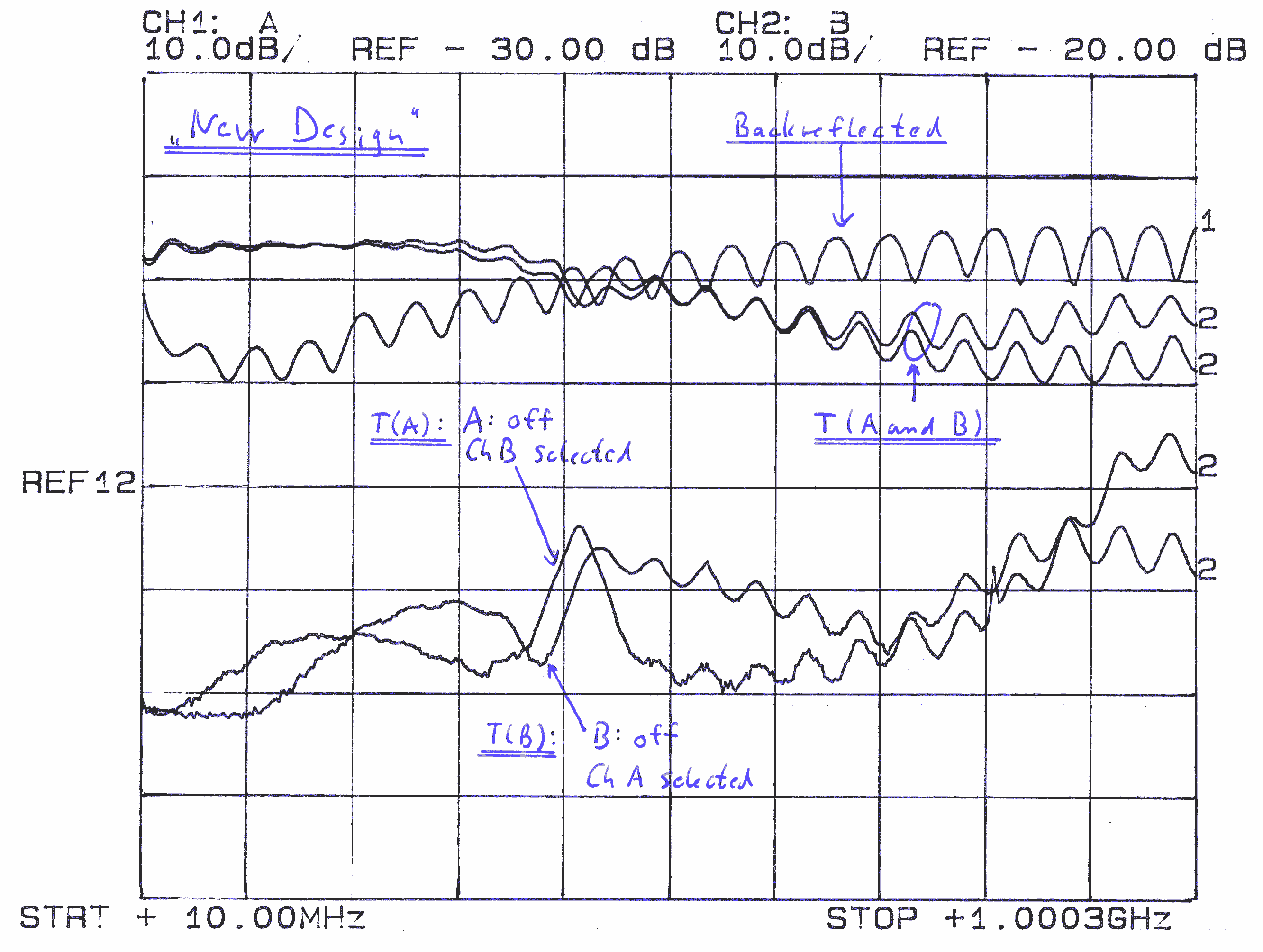
The "feature" in the T(A):A-off:B-On trace at around 440MHz went unnoticed,
but got
important later...
...as in the second iteration there was a mysterious crosstalk from the
inactive to the active channel.
Shown here is the trace of Ch1
while the inactive Ch2 is fed with a 2 DIV square wave:

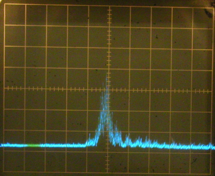
After two unsuccessful nights of search, the spectrum analyzer revealed, that
the inactive stage was oscillating
at over 500MHz and this was the reason
for the crosstalk. Essentially V2.0 used way to fast transistors
for
the sloppy setup within the C1-122. Power spectrum of
the oscillating replacement (f centered at 530MHz):
The result was V3.0 with an optimized design and PCB layout...
4. Related information
• There is a shop online, still selling the C1-122 oscilloscope:
www.hupra.com
• Thanks to Holm Tiffe, who has lot of cool stuff in his
shop (e.g. nice tubes)
and many thanks for supplying the tiny replacement
transistors.
• In a German microcontroller forum there is a thread...
"C1-91 owner wanted"
...where some people are discussing the C1-91 which is very similar to the
C1-122. E.g. Olaf, who is doing a
great job in restoring vintage radios
and much more, is replacing the HV
supply of his scope with modern components.
• There are schematics
for the C1-70 online at this address:
http://www.jais.ru/C1-70-rem.html
• In Dresden Gerald
Staats is working on a replacement, too. Thanks for him supplying
the datasheets of the transistors and I am looking
forward to his replacement since he is
very skilled in RF technology and his product will surely better
than mine.
• This page shows
an opened hybrid device and lists that the 04KN009 is also used
on the
following oscilloscopes:
C1-114,
C1-117:
http://www.155la3.ru/04kn009.htm
•
A Russian page showing
nice pictures of various hybrid devices (among them the
04KH009) and a
replacement as well. No detailed data is given on performance
http://ab2000.by.ru/b_sbor.html
• Some of the fancy plug-ins
for this oscilloscope are depicted here (scroll down!):
http://www.salpas.com/LT/katalog/oscilografai
5. Source for original parts
End of 2011 Alexander Shalygin
from Dnepropetrovsk in the Ukraine contacted me and he has
lot of new, original 04KN009s
in stock for
sale! I am sure these are the easiest way to
restore your USSR equipment.
Feel free to contact Alexander regarding 04KN009s at
kip -at- dp.farlep.net!
Many thanks
to him - as he sold some of them to me.
I certainly will keep and cherish them . . . just in case ;-)
Alexander's stock of 04KN009:
Mid of 2020, Holm pointed me to Evita in Vilnius, Lithuania who have
significant quantity of the 04KN009 in
stock
- Thanks for the hint!
6. Future
Starting from 2016, the oscilloscope is not only used for regular electronics work, but
it also serves as x-y-display: Inserting the amplifier module Я4C-90 on the very
hand right side
instead of the deflection plug-in Я4C-91, allows control of 4 spots simultaneously!!
This facility is used as a vector display for e.g. running a port of the first computer game,
SpaceWar! on a vintage Rolm/Loral 1602 mil-spec
computer, compatible to the DG Nova:
This is part of my vintage computer and avionics hobby - if interested have a look at
my logbook.
To make the C1-122 an even better x-y-display, it will
need a blanking input, which will require some modifications of the unit and an additional
input on the rear side...
Stay tuned... 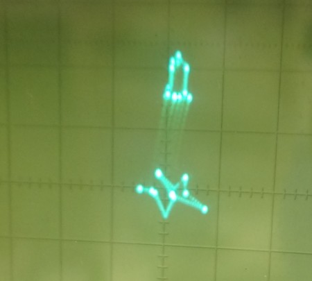
erik@baigar.de, www.baigar.de, Impressum,